veh-heli-01 · pad · hangar · charge dock

Flight Ops

The first thing in this city with rotors. Five kilograms, a 1.8 m coaxial rotor, and air at 1.7% of Earth's density — which makes hovering cost roughly twice the power it would take on Earth despite weighing 2.6× less. Every second of its 80 s survey loop is a closed-form function of time, and the battery, not the aerodynamics, decides whether it flies today.

Hover, 5 kg
604 W rotor · 805 W elec
Rotor
1,698 rpm · tip Ma 0.667
Baked loop
80 s 269 revs · closes exactly
Cold start
−20 °C trips in 1 s · 23 min preheat
01

A helipad east of the print works

Pad, hangar, charge dock and one aircraft — Ingenuity's grandchild, sized for city errands.

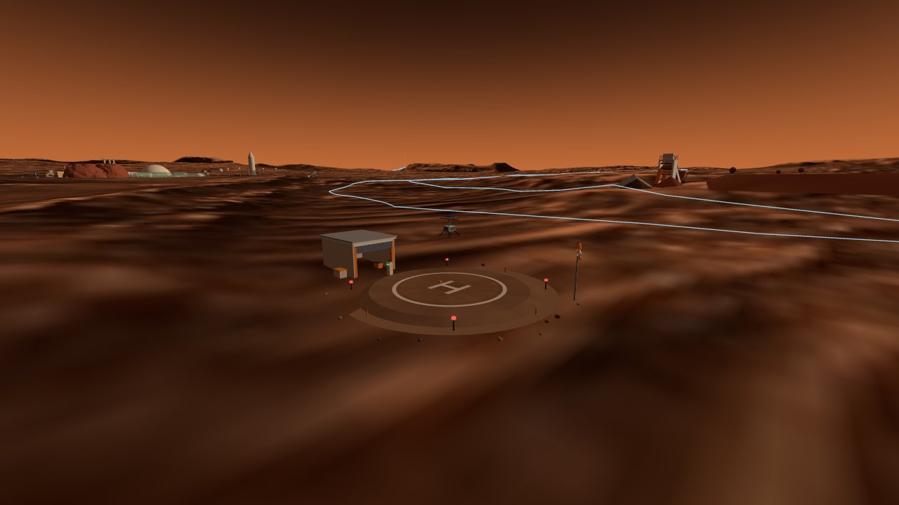
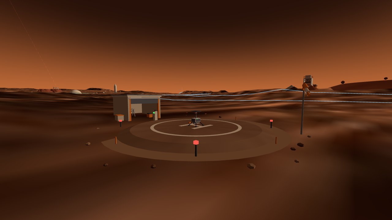
The whole installation is a single asset at (150, −40): a 10 m sintered-regolith disc with an H marking and four blinking approach lights, a shed with a half-rolled door holding a spare-blade rack, a charge post cabled to the pad, and a windsock that hangs limp almost always — at 8 m/s the Martian dynamic pressure is 0.54 Pa against the ~30 Pa it would take to inflate it.

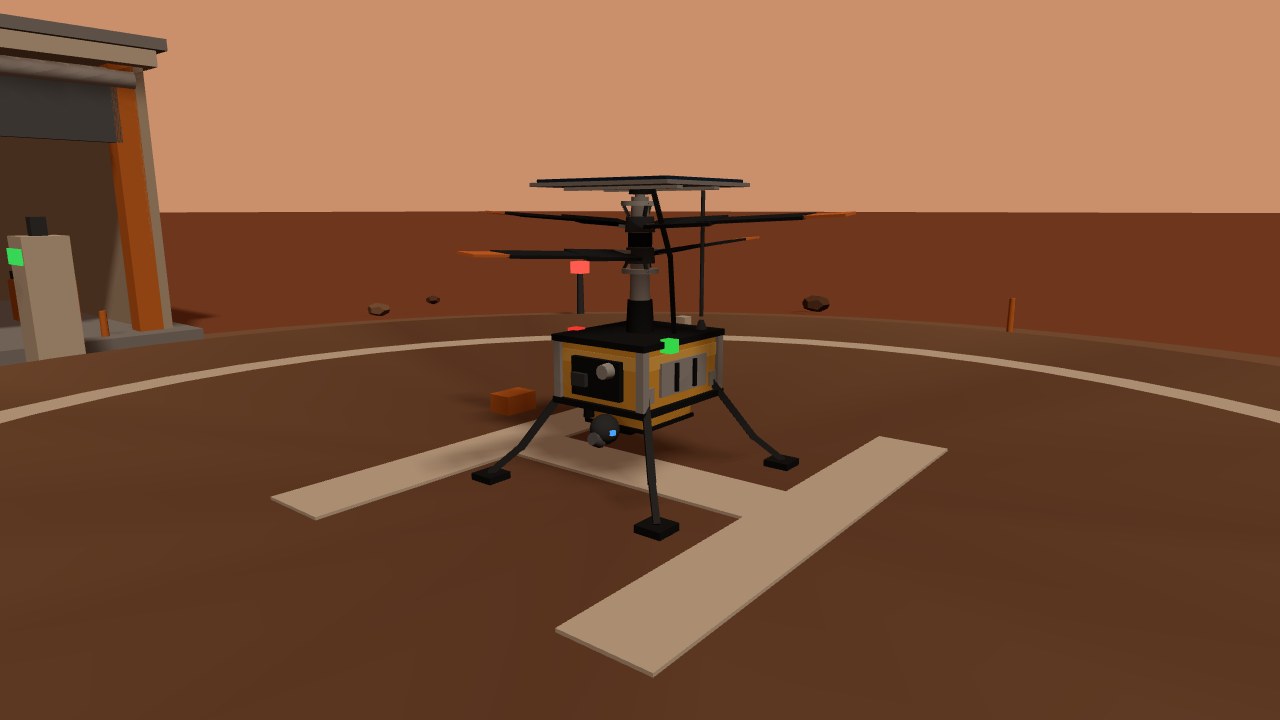
The aircraft is a coaxial twin-rotor scout, 5.0 kg gross, 1.8 m rotor diameter, on the Ingenuity → Mars Science Helicopter line. Gold MLI blanket over a carbon-decked fuselage, solar panel on the mast head, camera gimbal and laser altimeter on the belly, four compliant legs. Its beat is the stuff nobody can walk: the 429 m radiator array, the pipeline corridors, and a fast citywide survey after every dust storm.

Recharge comes off the city grid, not the sun. That single fact separates it from the real Ingenuity, which waited a sol on solar between 90-second hops: here a sortie costs 131 Wh and the dock puts it back in minutes. The mast panel is a trickle heater and a limp-home reserve, nothing more.

The scout helicopter lifting off its sintered pad next to the hangar, city on the horizon
VEH-HELI-01 — LIFTOFF FROM THE SINTERED PAD. HANGAR AND CHARGE DOCK LEFT, WINDSOCK RIGHT, CITY ON THE HORIZON.
Close view of the airframe: gold MLI fuselage, twin swashplates, three-segment blades, two-segment legs
AIRFRAME — GOLD MLI BOX, TWIN SWASHPLATES WITH SIX PUSH-RODS, THREE-SEGMENT TWISTED BLADES.
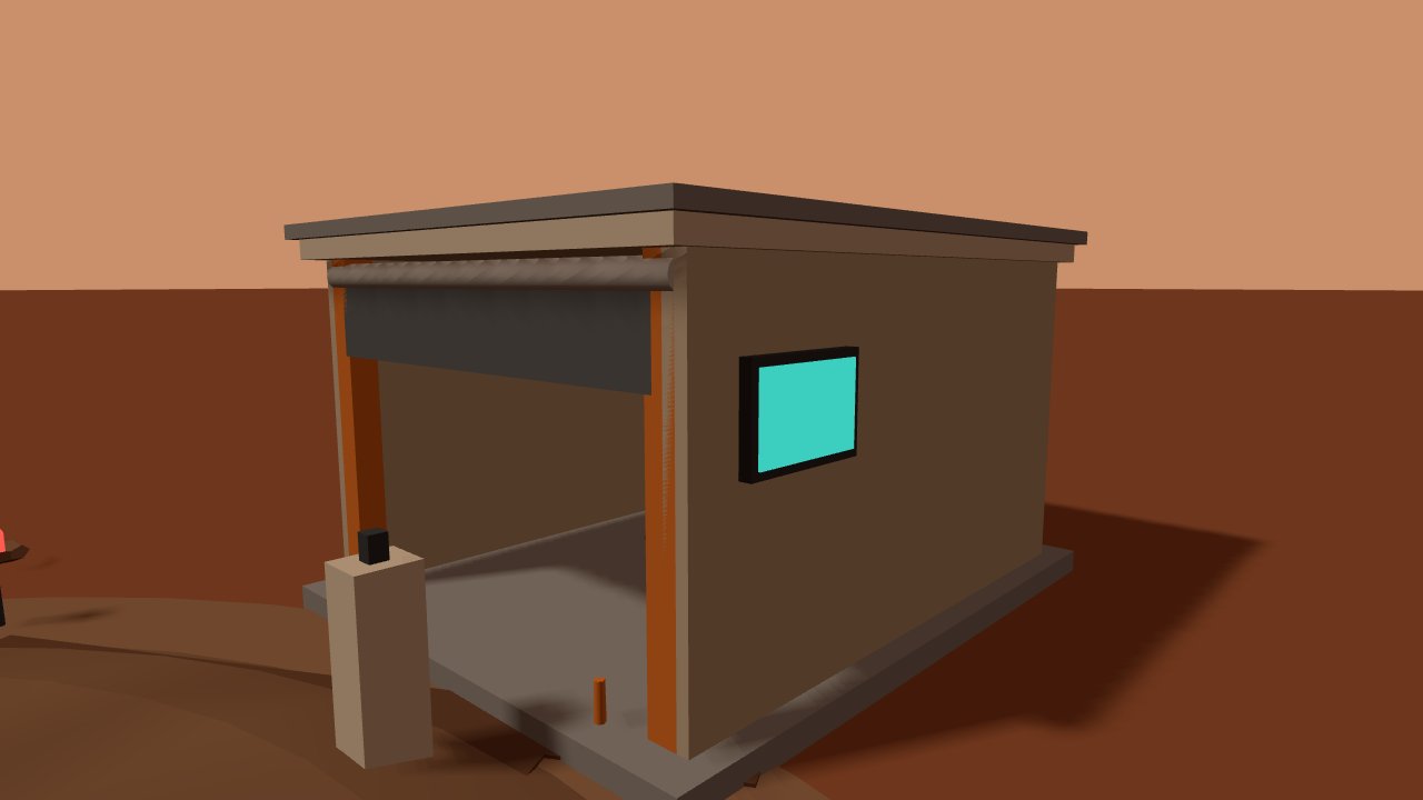
The hangar with rolled door, status screen and spare-blade rack
HANGAR — SPARE-BLADE RACK INSIDE. BLADES ARE A LOW-RE CONSUMABLE; PACKS GET SWAPPED ONCE A MARS YEAR.
02

What hovering costs in 0.6% air

Three ledgers set the whole airframe: momentum theory, the speed of sound in cold CO₂, and the Reynolds number of a blade the size of a ruler.

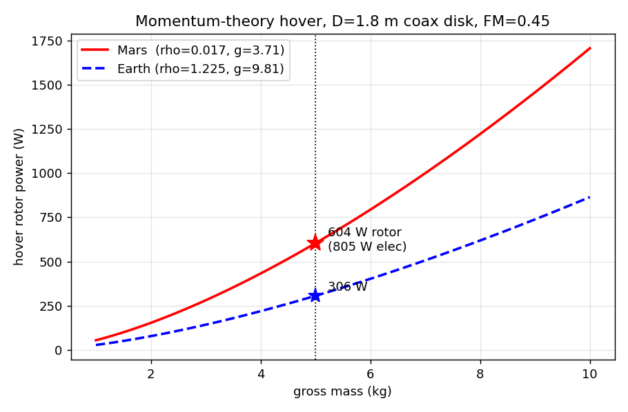
Momentum theory first. Weight is 18.55 N over a 2.545 m² shared coaxial disc, so disc loading is 7.29 N/m² — and at ρ = 0.017 kg/m³ the rotor must throw that thin air downward at an induced velocity of 14.6 m/s. Ideal induced power is 272 W; with a figure of merit of 0.45 (honest for this Reynolds regime) the shaft needs 604 W, and the motors draw 805 W. The same airframe on Earth would need an induced velocity of just 2.8 m/s and 306 W. Mars makes it weigh 2.6× less and still costs 5.2× the power per newton of lift — because induced velocity scales as 1/√ρ, and 72× thinner air beats 2.6× weaker gravity every time.

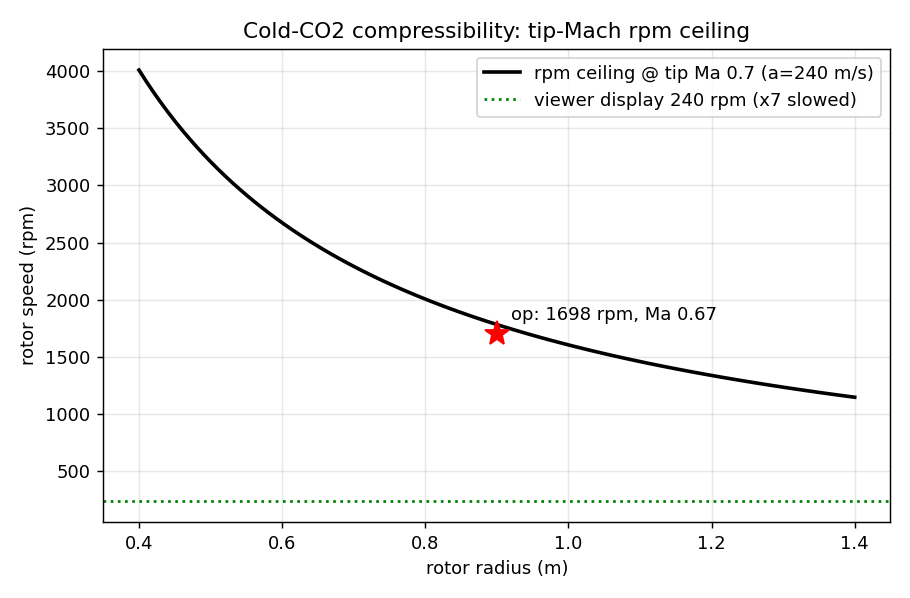
Then compressibility. Cold CO₂ carries sound at only ~240 m/s, roughly 70% of Earth's, so the blade tips hit their Mach wall early: capping tips at 0.7 Ma allows 1,783 rpm at R = 0.9 m. The design sits just below it at 160 m/s tip speed — 1,698 rpm, Ma 0.667, blade loading CT/σ = 0.118. In the viewer the rotors turn at 240 rpm, exactly 1/7.1 of truth: at the real rate a 60 fps frame advances the blade 170° and the rotor reads as a stationary blur. Both numbers are written on the card.

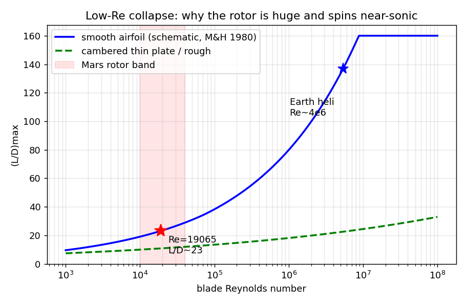
And the reason the rotor is so big in the first place: at 0.10 m chord and 120 m/s the blade Reynolds number is 1.9 × 10⁴ — an Earth helicopter blade runs near 5 × 10⁶, a factor of 280. Below Re ≈ 7 × 10⁴ laminar separation collapses smooth-airfoil lift-to-drag from O(100) to about 20, and cambered thin plates start winning. Big disc, near-sonic tips, wide thin blades: all three walls push the same way, which is why the rotor dominates the vehicle instead of decorating it.

Hover rotor power versus gross mass, Mars against Earth
MOMENTUM-THEORY HOVER — 604 W ROTOR AT 5 kg ON MARS vs 306 W ON EARTH, SAME AIRFRAME.
Rotor speed ceiling versus radius at tip Mach 0.7, with the operating point and the display rate
TIP-MACH CEILING — 1,783 rpm AT R = 0.9 m; OPERATING POINT 1,698 rpm, DISPLAYED AT 240.
Maximum lift-to-drag versus Reynolds number, showing the collapse below 7e4 and the Mars rotor band
LOW-RE COLLAPSE — BLADE Re 1.9 × 10⁴ SITS INSIDE THE BAND WHERE SMOOTH AIRFOILS STOP WORKING.
03

The loop, and the balance behind it

Eighty seconds of flight written as a pure function of time — and a power balance that had to agree with a completely separate simulation.

The flight is baked: position, heading, rotor angle and attitude are closed-form functions of t mod 80 with smoothstep blends, never integrated state. Drop into the timeline at any instant and the aircraft is exactly where physics says it should be; the loop wraps seamlessly because the rotor turns exactly 269 revolutions per cycle (spin-up parabola, constant, spin-down parabola), verified by comparing the full transform tree at t = 0 and t = 80 — maximum matrix difference 0.

0–3 s
Parked, rotors still
3–9 s
Spin-up
9–17 s
Vertical climb to 32 m
17–63 s
Tangent out, 73 m circuit of the mine, tangent home
63–71 s
Decelerating descent
71–75.5 s
Touchdown, spin-down
75.5–80 s
Parked again

Obstacle clearance was sampled, not assumed. Seventy points along the route were queried against the real terrain heightmap inside the running engine: the highest ground under the track is 48.7 m, the pad sits at 40.7 m, and cruising at 32 m AGL puts the aircraft 24.0 m above the worst terrain against a 15 m rule. Laterally the patrol circle clears the mine's measured bounding box by 20.1 m against a 20 m rule — a margin that took a rework to earn (see below). A full-cycle envelope sweep at 0.05 s steps over every mesh confirms nothing ever dips into the ground.

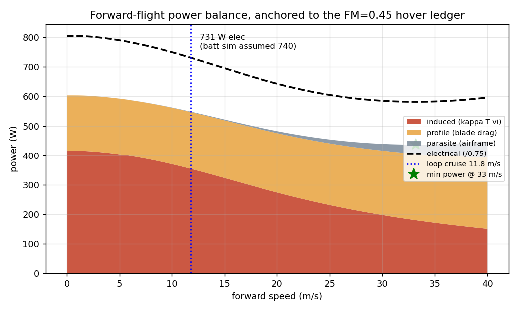
Then the part that had been missing: an actual power balance. Forward-flight power splits into induced (Glauert), profile (blade drag, growing with μ²) and parasite (airframe), calibrated so that V = 0 reproduces the hover ledger exactly — the FM 0.45 figure decomposes into κ = 1.53 and Cd0 = 0.06. At the loop's 11.8 m/s cruise the split is 354 + 193 + 1.4 W, giving 731 W electrical. The battery simulation, written independently and days earlier, had assumed 740 W: the two paths agree to −1.2%. The parasite term being 1.4 W is the Martian punchline — in 610 Pa there is almost nothing to push against, the U-curve's right branch barely lifts, and minimum power sits way out at 33 m/s. Cruising at 12 m/s is a navigation and gust-margin decision, not an aerodynamic optimum.

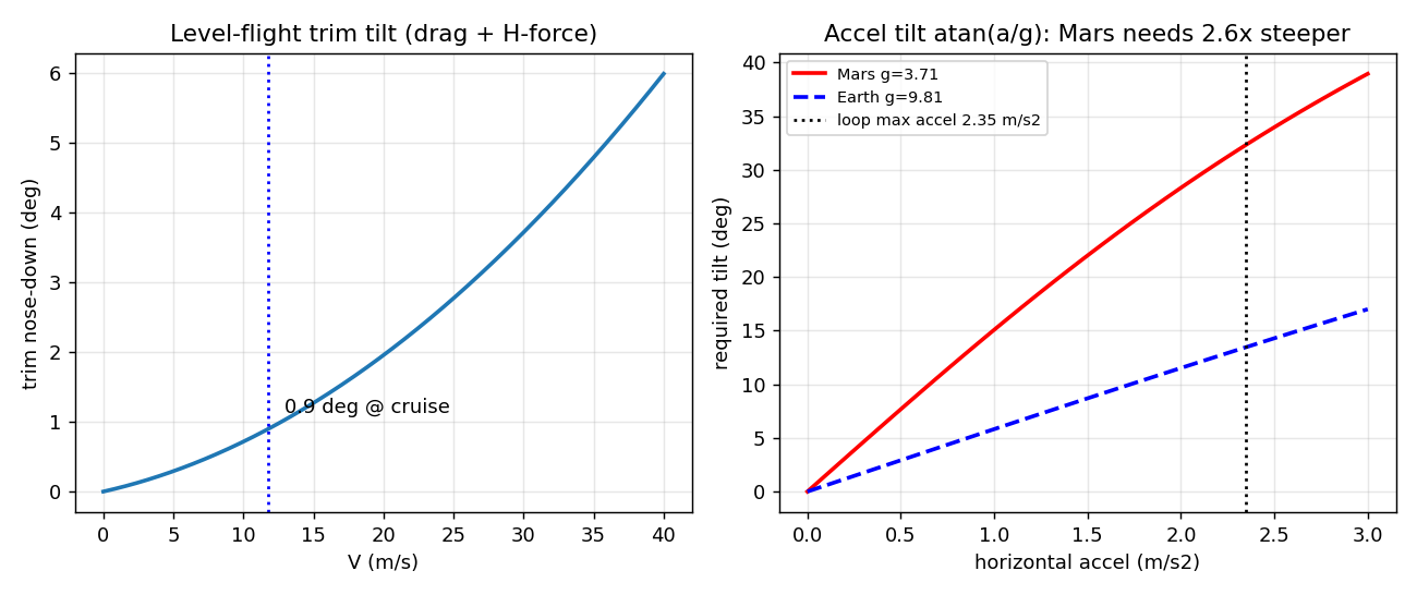
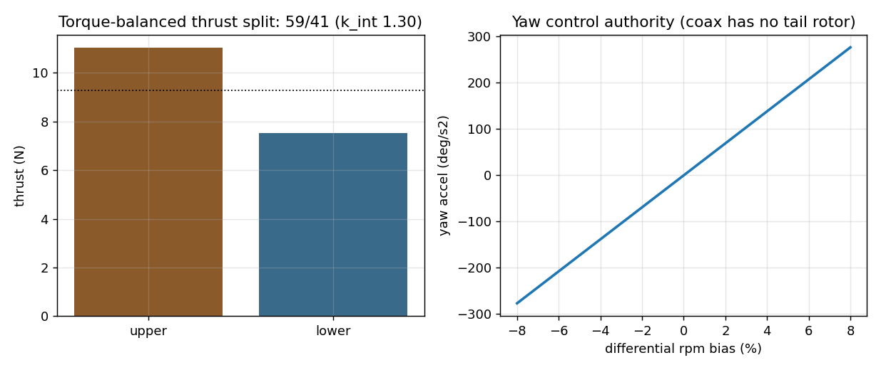
Trim closes it. Level flight needs only 0.9° of nose-down; but accelerating at 2.35 m/s² demands atan(a/g) = 32.4° where Earth would need 13.5° — low gravity makes every Martian maneuver visibly steeper. The baked loop shows the trim angle at its physical value and caps the acceleration tilt near 14°, the same declared display convention as the 1/7.1 rotor rate. On the coaxial pair, the lower rotor eats the upper's contracted wake, so torque balance at equal rpm splits thrust 59/41 with an interference factor of 1.30 against an isolated pair — Leishman's classic 1.28 corroborates the model. With no tail rotor, yaw is differential rpm: a ±5% bias gives 0.34 N·m and 173°/s².

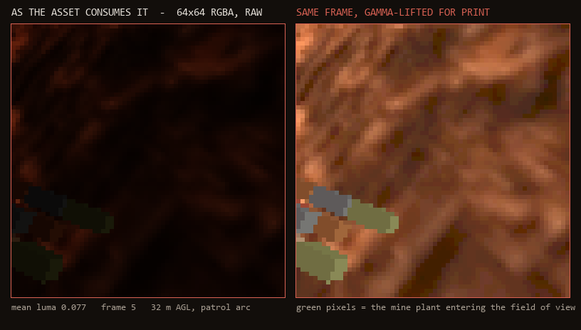
Underneath the aircraft is a 64 × 64 navigation camera at 2 Hz declared through the engine's sensor channel — the same mechanism the mine excavator and the undercity humanoid use. The engine renders it offscreen on budget and hands back raw RGBA; the asset reads mean luma and drives its gimbal indicator with it. In a 100 s in-engine test the channel delivered 195 frames. If an engine has no sensor channel at all, the same file falls back to the baked loop — graceful degradation is a hard contract here.

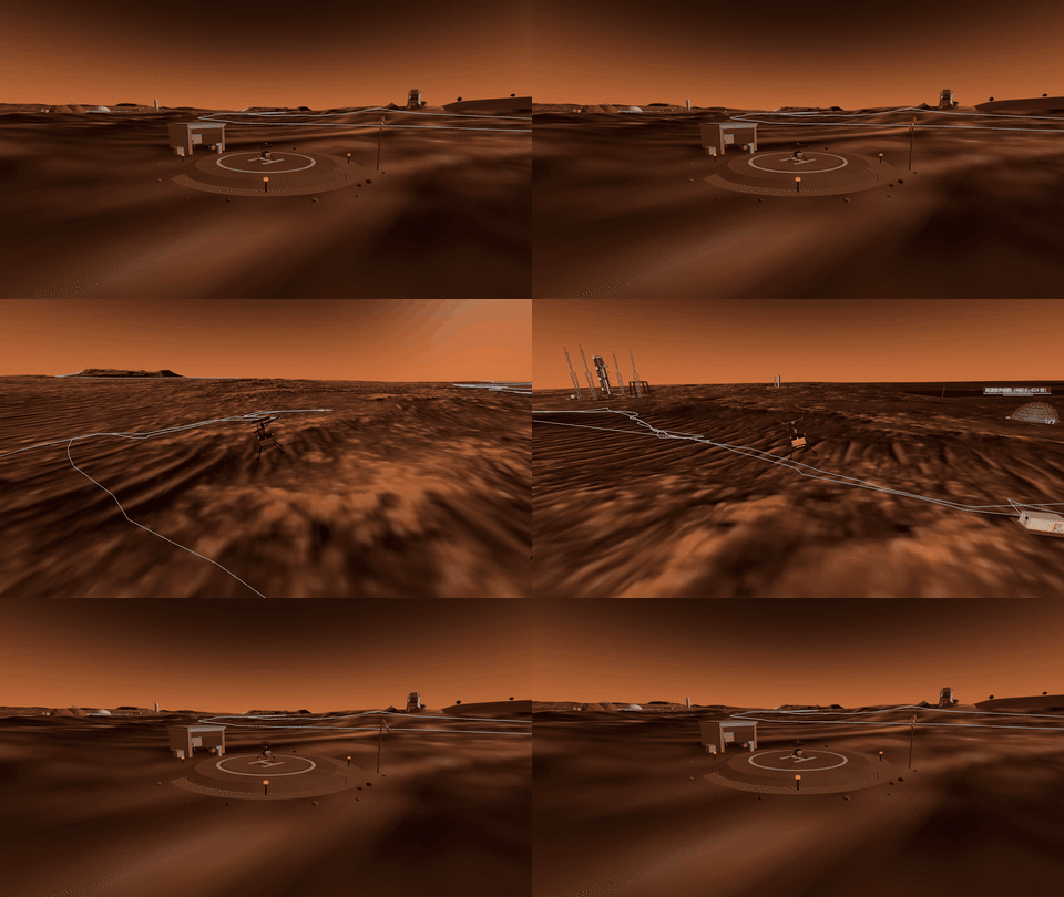
The full baked flight loop: liftoff, chase view around the patrol circuit, and landing
ONE FULL SORTIE — LIFTOFF, PATROL CIRCUIT, APPROACH AND TOUCHDOWN. CAPTURED FRAME-BY-FRAME FROM THE RUNNING CITY.
Forward-flight power decomposition into induced, profile and parasite
P(V) — 731 W AT CRUISE vs THE BATTERY SIM'S ASSUMED 740 W. PARASITE POWER IS 1.4 W.
Trim tilt versus speed, and required acceleration tilt on Mars versus Earth
TRIM 0.9° LEVEL · ACCEL TILT 32.4° AT 2.35 m/s² — 2.4× STEEPER THAN EARTH FOR THE SAME PUSH.
Coaxial torque-balanced thrust split and yaw authority versus differential rpm
COAX BALANCE — 59/41 THRUST SPLIT, ±5% RPM BIAS BUYS 173°/s² OF YAW.
The navigation camera frame as the asset consumes it, raw and gamma-lifted
NAV CAM AT 32 m — RAW 64×64 AS CONSUMED (LEFT), GAMMA-LIFTED (RIGHT). THE GREEN PIXELS ARE THE MINE.
04

The battery decides when it flies

A cold lithium pack on Mars does not die of energy. It dies of power, one second into spin-up.

The pack is eighteen 18650 power cells in 6s3p: 1.10 kg all-in with BMS, busbars, film heater, aerogel and shell — 194 Wh, 177 Wh/kg. Hover pulls 37 A, which is 4.1C per cell and leaves only 1.21× headroom against the continuous rating; that headroom is the entire reason for the third parallel string.

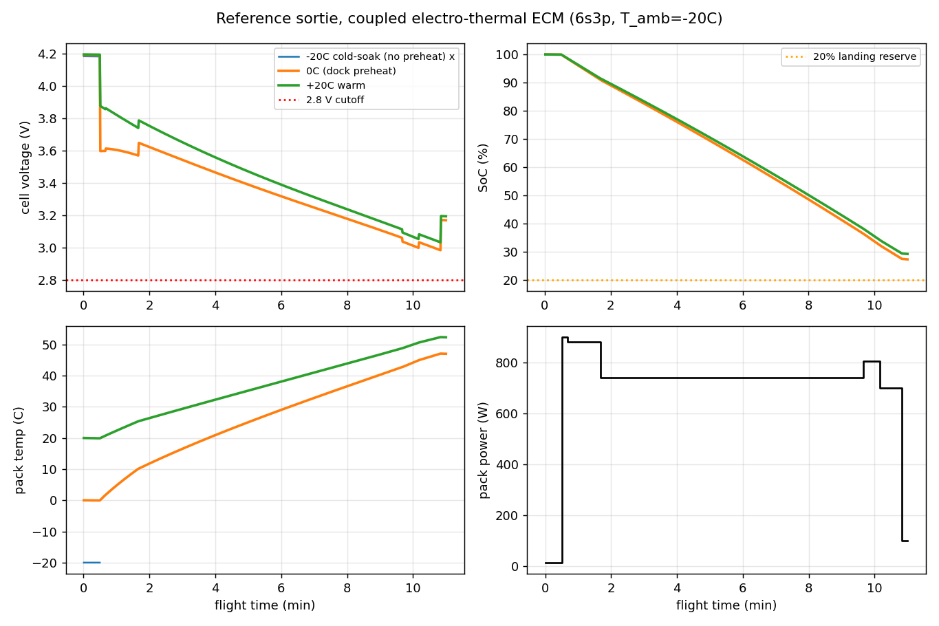
Discharge was simulated as a coupled electro-thermal ECM — an OCV(SoC) curve with an Arrhenius internal resistance — over the full 130.7 Wh sortie profile. Started from a −20 °C cold soak, the pack trips its 2.8 V cutoff one second into spin-up: resistance is 3.7× its room-temperature value and the 900 W spin-up transient simply cannot be delivered. Preheated to 0 °C on the dock, the same sortie completes, lands at 27.3% SoC, and along the way I²R self-heating carries the pack from 0 °C to 47 °C — the R(T) coupling is self-regulating, and it stays well under the 70 °C limit. Usable energy works out to 131 of 194 Wh, i.e. 67.5%, which is what the earlier 70% derate assumption had been standing in for. That buys 9.8 minutes of hover, 10.6 of cruise, 7.6 km of range and a ~3.1 km recon radius.

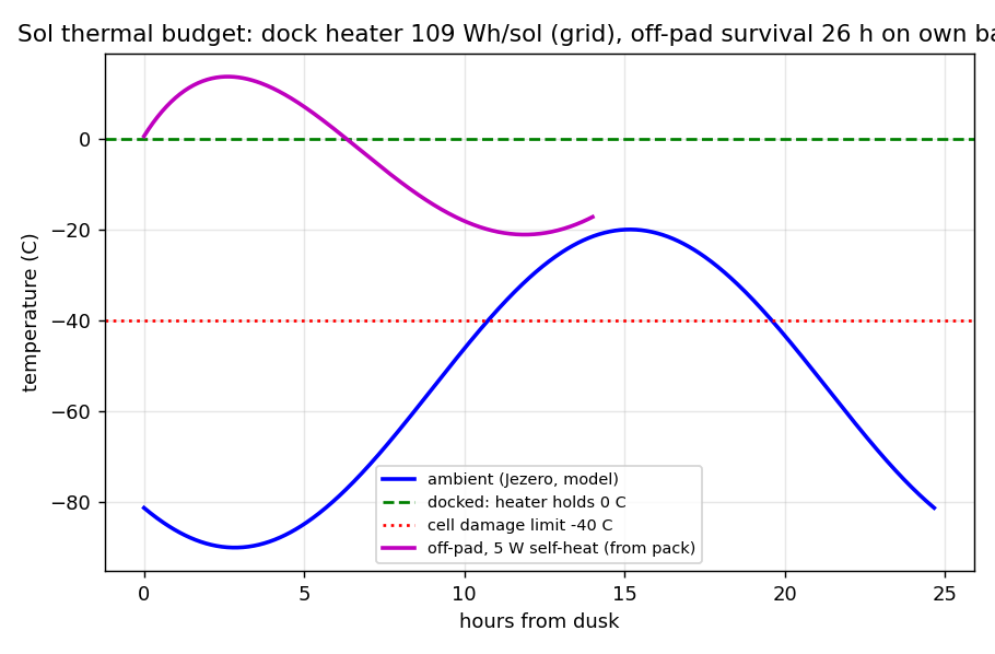
The thermal budget explains the operating rules. Under 10 mm of aerogel the pack leaks 0.08 W/K, so holding it at 0 °C overnight on the dock costs 109 Wh per sol (4.4 W average) — grid power, trivially affordable. Stranded off the pad it is another story: unheated it reaches the −40 °C damage line in 4.5 hours, and self-heating at 5 W survives 26 hours but consumes the entire pack. That single number is why a downed aircraft is a same-sol recovery, not a tomorrow problem. Cycle life closes the loop at 0.027% fade per 70%-DoD cycle: 740 sorties to the 80% line, 82% left after a Mars year of daily flying — one pack swap per Mars year, filed next to the spare blades.

Three things the lumped model was hiding

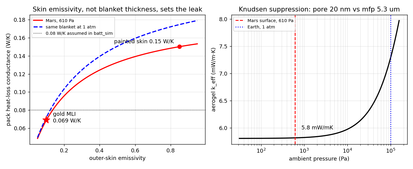
That 0.08 W/K was an assumption, and three operating rules were hanging off it — so it got derived. At 610 Pa the CO₂ mean free path is 5.3 µm against a 20 nm aerogel pore: Knudsen number 265, gas conduction suppressed to 0.01 mW/(m·K) where the same blanket on Earth would carry 1.49. The blanket therefore costs almost nothing — and the real bottleneck is the skin radiating to the sky. With the gold MLI at ε ≈ 0.1 the pack leaks 0.069 W/K; with an ordinary painted skin it would leak 0.15. The gold film is doing thermal work, not just cosplaying Ingenuity. The assumed number was 14% conservative: docked heating is really 94 Wh/sol and unheated survival 5.0 h — the same-sol recovery rule survives its own correction.

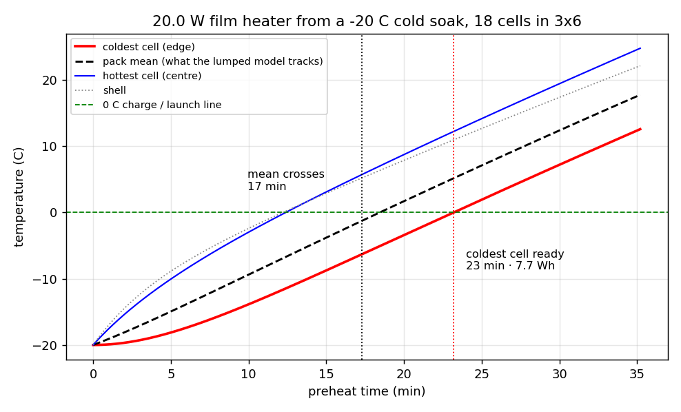
Second, "preheat before you fly" never had a duration. On an 18-cell 3×6 thermal network with a 20 W film heater from a −20 °C soak, the coldest edge cell needs 23 minutes and 7.7 Wh to cross 0 °C, and at that moment there is 12.2 K of spread across the pack. A single-node model watching the mean would have cleared the aircraft at 17 minutes — 26% optimistic, and the cell that trips the cutoff is never the average one.

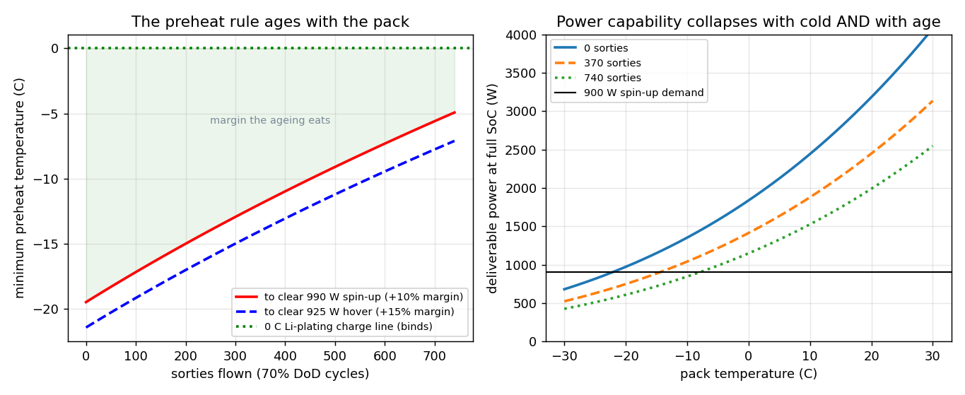
Third, the 0 °C rule was written for a new pack. End-of-life resistance is 60% higher, which lifts the minimum temperature for the 900 W spin-up transient from −19.5 °C to −4.9 °C — 14.5 K of margin eaten by age. It never crosses zero, and that is the useful result: the 0 °C line is a charging constraint (lithium plating on the anode), not a power one, and it stays valid for the whole life of the pack.

Pack heat-loss conductance versus skin emissivity, and aerogel conductivity versus ambient pressure
KNUDSEN-KILLED GAS CONDUCTION — THE LEAK IS SET BY SKIN EMISSIVITY: 0.069 W/K GOLD vs 0.15 PAINTED.
Preheat transient showing coldest cell, mean and hottest cell crossing the 0 C line at different times
PREHEAT FROM −20 °C — COLDEST CELL AT 23 min / 7.7 Wh; THE MEAN CROSSES 6 min EARLIER AND LIES.
Minimum preheat temperature versus sorties flown, and deliverable power versus temperature for three ages
AGEING — THE SPIN-UP LINE CLIMBS −19.5 → −4.9 °C OVER 740 SORTIES BUT NEVER REACHES THE 0 °C PLATING LINE.
Cell voltage, state of charge and pack temperature across the sortie from three start temperatures
SORTIE DISCHARGE — THE −20 °C CASE ENDS AT t = 1 s. THE 0 °C CASE SELF-HEATS TO 47 °C AND LANDS AT 27.3%.
Sol temperature cycle with docked heater line and off-pad self-heating survival curve
SOL THERMAL BUDGET — 109 Wh/SOL ON THE DOCK; 26 h OF SELF-HEAT OFF IT, AT THE COST OF THE WHOLE PACK.

Landing on the plug

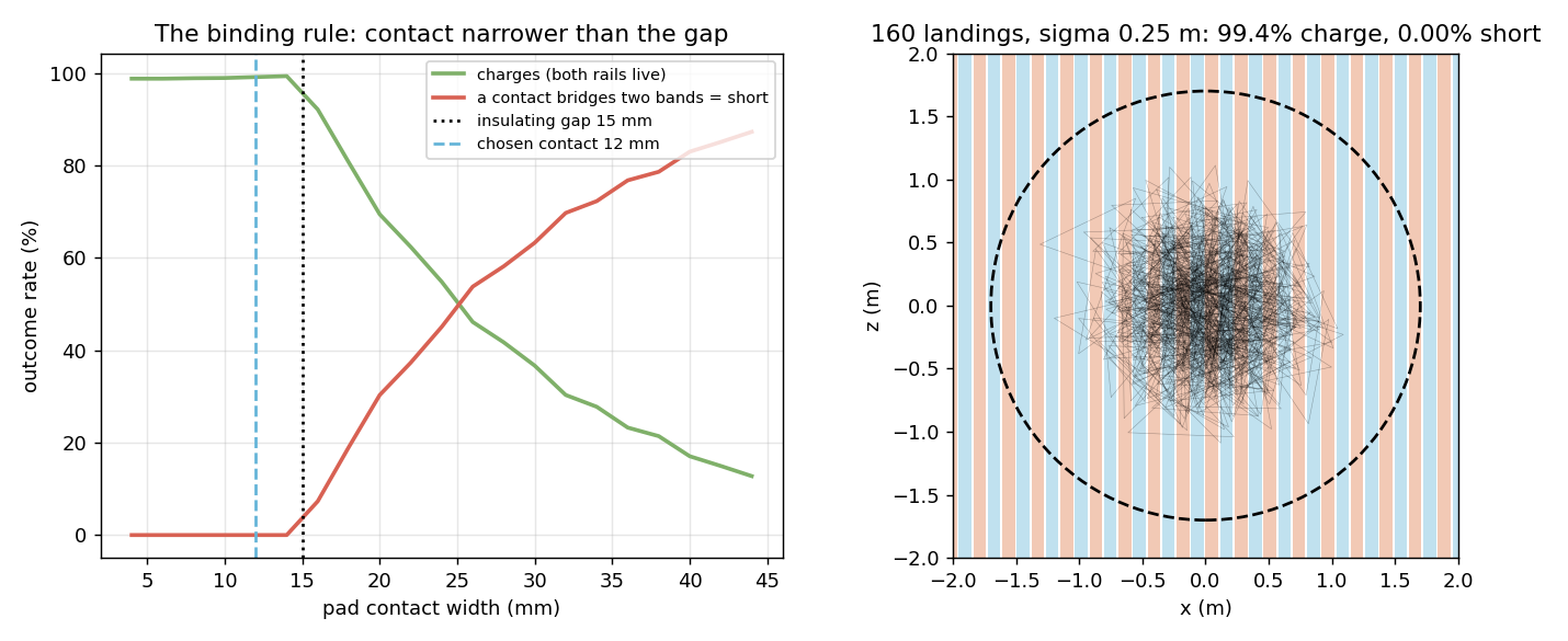
A connector needs ±5 mm of alignment. Landing dispersion is 250 mm, 1 σ per axis — two orders of magnitude apart, so a plug would need a funnel or a robot arm, i.e. one more mechanism to freeze shut in the cold. The pad instead carries an alternating-polarity electrode floor: 100 mm conductor bands separated by 15 mm insulating gaps, and two 12 mm gold contacts under each foot pad. Touchdown is the connection.

The first version of that floor shorted three landings out of four. It was sized on the obvious rule — bands wider than the foot pad — and a 110 mm pad simply walks across a 40 mm gap and bridges both polarities: 20,000 simulated landings returned 76.7% shorts. The binding rule is not band > pad, it is gap > contact. Splitting each pad into two 12 mm contacts (smaller than the gap, so one contact can never bridge two bands), spacing them half a period apart so the pair always straddles opposite polarities, mounting the pairs on legs 1/3 and 2/4 at right angles so some pair always crosses the stripes, and giving every contact its own diodes turns the same floor into 99.4% first-try connection with zero shorts, at any heading, with 7.8 contacts live on average. The remaining 0.6% hops and re-lands.

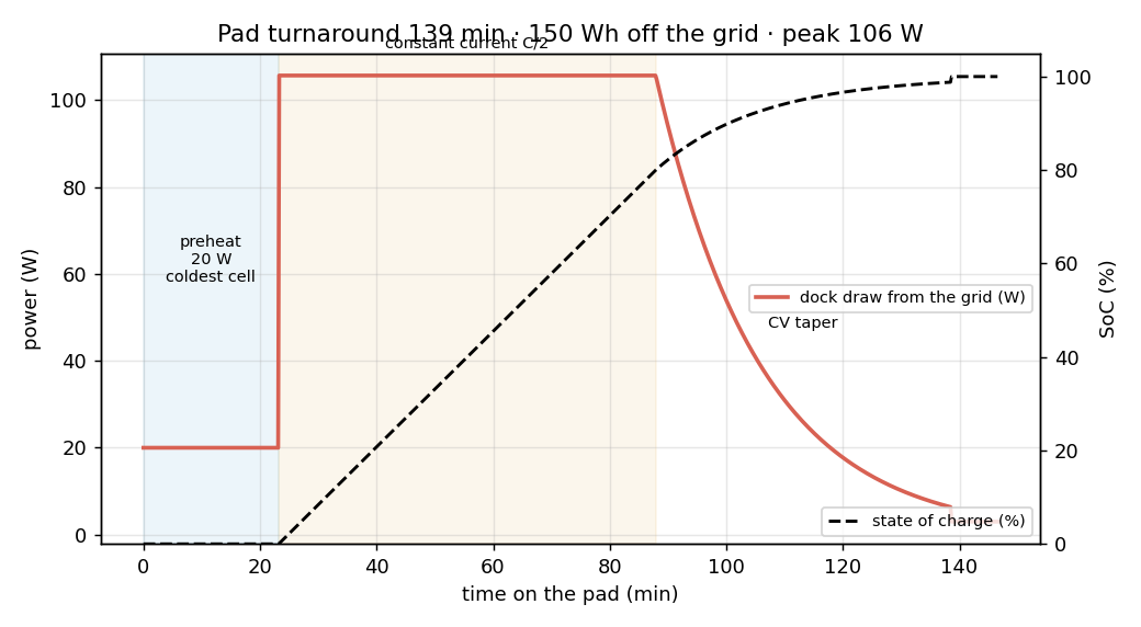
Contact physics is comfortable: 4.64 N per pad gives a 136 µm Holm constriction spot and 1.09 mΩ per pad, so the loop drops 9.8 mV at 4.5 A and wastes 0.04 W. Against a 2% voltage budget there is 44× headroom for dust film — and every touchdown wipes the gold. Upstream, the cabinet serialises the job: 20 W of preheat for 23 min, then C/2 for 65 min, then a 51 min CV taper — a 138 min turnaround at a 100 W peak, which keeps the pad on a light branch circuit. A 200 Wh buffer brick holds the pack at 0 °C for 53 h if the feeder browns out, because the storm that grounds the aircraft is the same storm that takes down the grid.

Connect and short rates versus contact width, and 160 simulated landings over the stripe map
CONTACT NARROWER THAN THE GAP — 99.4% CONNECT, 0% SHORT OVER 20,000 LANDINGS AT σ = 0.25 m.
Dock power draw and state of charge across preheat, constant current and CV taper
PAD TURNAROUND — PREHEAT, THEN C/2, THEN TAPER: 138 min AND 143 Wh AT A 100 W PEAK.
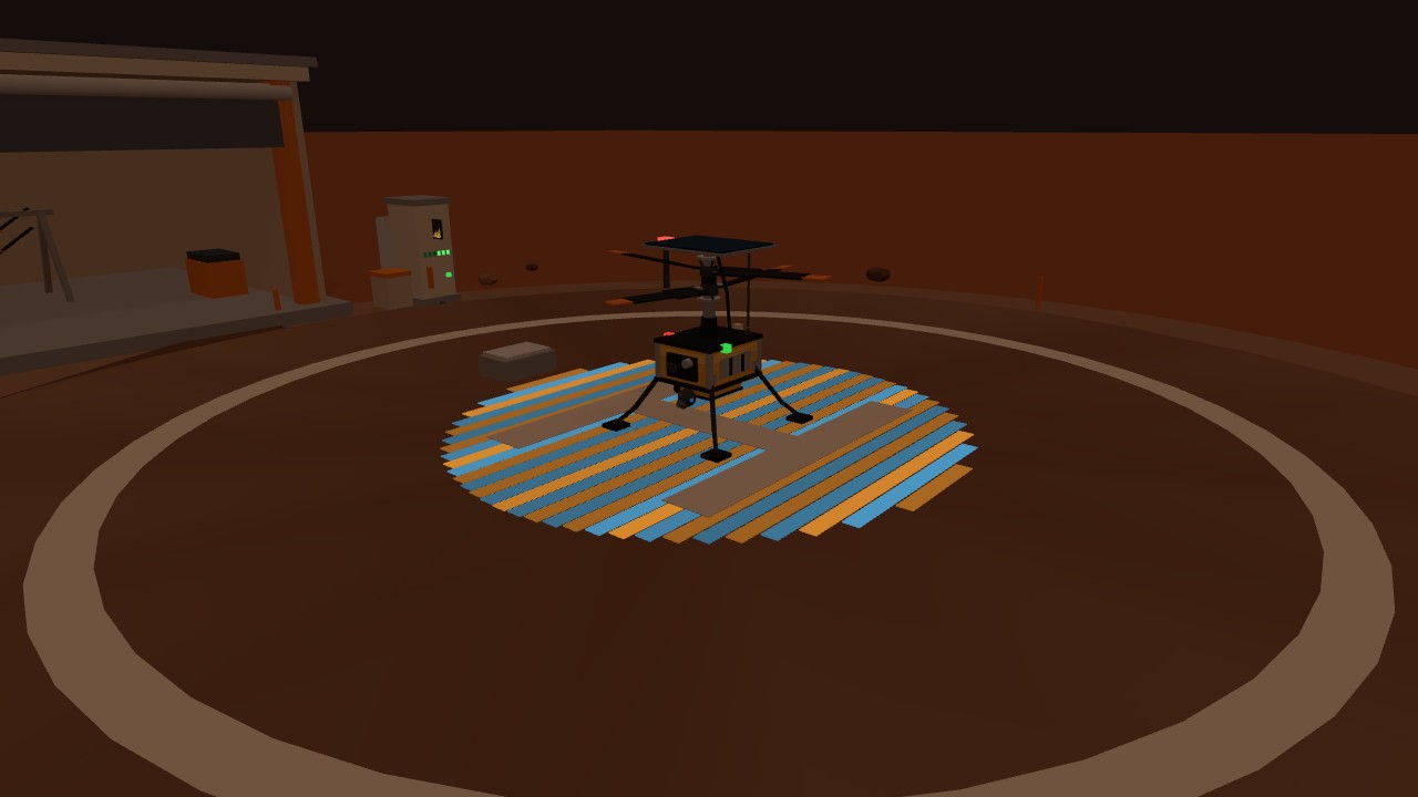
The electrode floor pulsing amber and blue at night while the helicopter charges
CHARGING AFTER DUSK — THE ONLY PATCH OF GROUND IN THE CITY THAT LIGHTS UP.

Why the floor runs at 21.6 volts

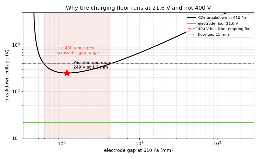
Any engineer trained on Earth reaches for the same fix when a link carries 4.5 A: step the voltage up, shrink the current, watch the I²R loss fall by two orders of magnitude. On Mars that instinct is a fire. Paschen's law has a minimum — breakdown voltage does not climb monotonically with gap, because too small a gap gives electrons no room to ionise and too large a one starves them between collisions — and at 610 Pa in CO₂ that minimum sits at 249 V across a 1.17 mm gap. A 1.17 mm gap is not hypothetical: it is what opens between contact and band every single time the aircraft lifts off.

At 21.6 V the floor has 11.5× margin against that minimum and cannot strike an arc at any separation whatsoever (the 15 mm design gap would need 900 V). A 400 V bus would sit inside the breakdown window from 0.59 to 4.3 mm — precisely the range the contacts sweep through on every landing and departure. Low voltage and high current is not a compromise on this planet; it is the only safe corner of the map, and it is why the contact resistance ledger above had to be so careful.

The same physics sets the disconnect sequence. Silver contacts arc above 12 V and 0.4 A, the floor runs at 21.6 V and 4.5 A, and DC gives you no zero crossing to hide behind — separating under load would erode the gold plating that the 44× dust margin depends on. So the contacts never break current: converter soft-stops in 50 ms, contactor opens cold, bus bleeds down, and only then do the rotors get their spin-up command. The floor going dark 0.5 s before the blades move is not an art beat.

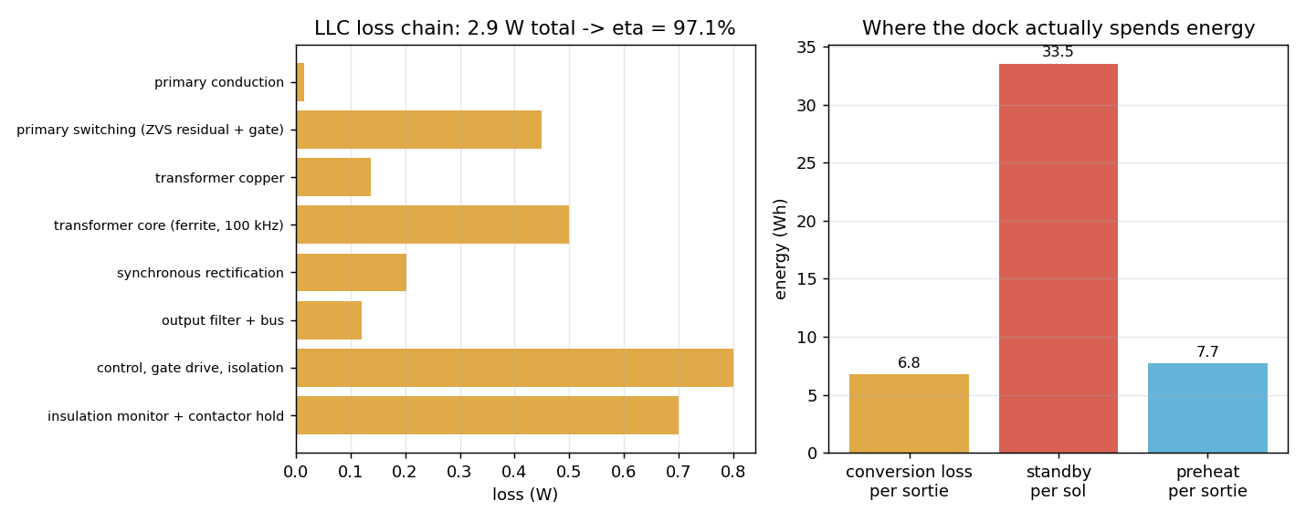
Opening the cabinet paid off one more debt. The 92% efficiency I had carried through every charging account was a placeholder; costing the isolated LLC stage term by term — switching, transformer copper and core, synchronous rectification, control, insulation monitor — gives 2.9 W of loss and 97.1%. Grid energy per sortie corrects from 150 to 142.6 Wh and the peak draw from 106 to 100 W. And the bottleneck immediately moved somewhere I had not been looking: conversion costs 6.8 Wh per charge, while idling the cabinet for the rest of the sol burns 33.5 Wh — five times more. Standby, not conversion, is what the dock actually spends energy on.

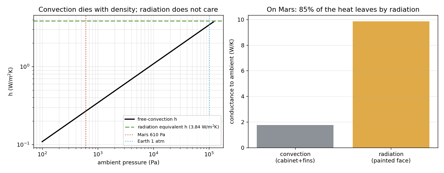
Finally, the cooling fins. At 610 Pa the Rayleigh number collapses from Earth's 5.8 × 10¹⁰ to 2.1 × 10⁶ — it scales as ρ² — leaving a convection coefficient of 0.27 W/(m²·K), so 85% of the heat leaves by radiation. Fins work by convection and mostly radiate into each other: the fins I had modelled were decoration, and they have been replaced by a high-emissivity panel. Not that it matters much — 2.9 W raises the cabinet by 0.25 K. Heat rejection was never the constraint. The cold end is: −93 °C nights are handled with −55 °C-rated parts and a 15 W, 10-minute local warm-up, because holding the whole cabinet warm overnight would cost 400 Wh/sol — more than three sorties of flight energy.

CO2 Paschen curve at 610 Pa with the 21.6 V floor and the 400 V bus breakdown window
PASCHEN AT 610 Pa — MINIMUM 249 V AT 1.17 mm, THE GAP EVERY TAKEOFF OPENS. 400 V WOULD ARC.
LLC loss breakdown and where the dock spends energy
LOSS CHAIN — 2.9 W, η = 97.1%. STANDBY (33.5 Wh/SOL) DWARFS CONVERSION LOSS (6.8 Wh).
Convection coefficient versus pressure and the conductance split between convection and radiation
CONVECTION DIES WITH DENSITY — 85% RADIATIVE, SO THE COOLING FINS WERE DECORATION.
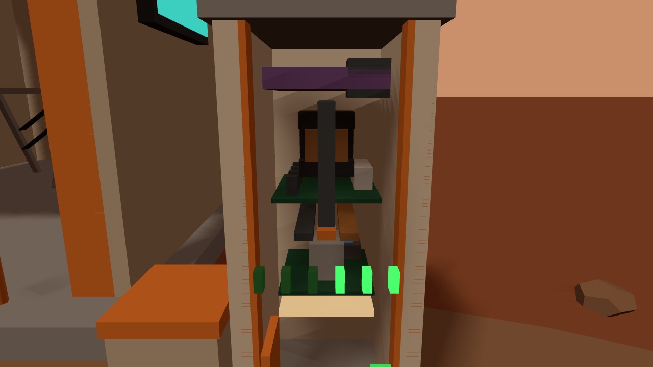
The charge cabinet cut open: violet high-voltage bar, isolation transformer, power and control boards, heater mat
CABINET CUT OPEN — 400 V BAR (VIOLET) → TRANSFORMER → COPPER LV BUS → CONTACTOR → CONTROL.

Weather grounds it before the battery does. Dust optical depth from the weather mast and SEP alerts from the radiation net share one alarm bus, and above τ ≈ 2 the aircraft stays on the pad — not for lack of lift (ρ barely changes in a storm) but because camera navigation and dust ingestion give out first. → Environment Watch

The pad at night with the four approach lights blinking and the hangar status screen lit
PAD AT NIGHT — FOUR APPROACH BEACONS ON THE ENGINE'S BLINK CHANNEL, DOCK AND STATUS SCREEN ON THE NIGHT-LIGHT CHANNEL.
05

The ledger

Every number on this page, and the run that produced it.

ClaimValueProduced by
Hover shaft power, 5 kg604 Wmars-heli/scripts/heli_design.py
Induced velocity in hover14.6 m/smars-heli/scripts/heli_design.py
Power per newton vs Earth5.2×mars-heli/scripts/heli_design.py
Rotor speed ceiling at tip Ma 0.71,783 rpmmars-heli/scripts/heli_design.py
Operating rotor speed / tip Mach1,698 rpm · 0.667mars-heli/scripts/heli_design.py
Blade Reynolds number1.9 × 10⁴mars-heli/scripts/heli_design.py
Cruise power, forward-flight balance731 Wmars-heli/scripts/heli_trim_sim.py
Agreement with the battery sim's assumption−1.2%heli_trim_sim.py × heli_batt_sim.py
Minimum-power speed33 m/smars-heli/scripts/heli_trim_sim.py
Level trim / accel tilt at 2.35 m/s²0.9° · 32.4°mars-heli/scripts/heli_trim_sim.py
Coax thrust split · interference factor59/41 · 1.30mars-heli/scripts/heli_trim_sim.py
Yaw authority at ±5% rpm bias173°/s²mars-heli/scripts/heli_trim_sim.py
Pack mass · energy · specific energy1.10 kg · 194 Wh · 177 Wh/kgmars-heli/scripts/heli_batt_sim.py
Cold-soak cutoff at −20 °C1 s into spin-upmars-heli/scripts/heli_batt_sim.py
Landing SoC · self-heating from 0 °C27.3% · 0 → 47 °Cmars-heli/scripts/heli_batt_sim.py
Usable energy fraction67.5% (131/194 Wh)mars-heli/scripts/heli_batt_sim.py
Endurance · range10.6 min · 7.6 kmheli_design.py × heli_batt_sim.py
Docked heater · off-pad survival109 Wh/sol · 4.5 h unheatedmars-heli/scripts/heli_batt_sim.py
Pack life to 80%740 sortiesmars-heli/scripts/heli_batt_sim.py
Aerogel k_eff at 610 Pa · Knudsen number5.8 mW/(m·K) · Kn 265mars-heli/scripts/heli_batt_deep.py
Derived pack conductance (gold MLI vs painted)0.069 · 0.15 W/Kmars-heli/scripts/heli_batt_deep.py
Docked heating · unheated survival, re-derived94 Wh/sol · 5.0 hmars-heli/scripts/heli_batt_deep.py
Preheat to 0 °C, coldest cell · spread23 min / 7.7 Wh · 12.2 Kmars-heli/scripts/heli_batt_deep.py
Spin-up temperature line, new → end of life−19.5 → −4.9 °Cmars-heli/scripts/heli_batt_deep.py
Electrode floor: connect · short (20k landings)99.4% · 0%mars-heli/scripts/heli_charge_sim.py
Rejected first floor design (band > pad)76.7% shortsmars-heli/scripts/heli_charge_sim.py
Contact drop · dust-film headroom9.8 mV · 44×mars-heli/scripts/heli_charge_sim.py
Pad turnaround · peak draw · energy138 min · 100 W · 142.6 Whmars-heli/scripts/heli_charge_sim.py
Paschen minimum, CO₂ at 610 Pa249 V at 1.17 mmmars-heli/scripts/heli_dock_core.py
Floor margin to breakdown · 400 V arc window11.5× · 0.59–4.3 mmmars-heli/scripts/heli_dock_core.py
LLC converter loss · efficiency2.9 W · 97.1%mars-heli/scripts/heli_dock_core.py
Standby vs conversion energy33.5 vs 6.8 Whmars-heli/scripts/heli_dock_core.py
Cabinet radiative share · temperature rise84.8% · 0.25 Kmars-heli/scripts/heli_dock_core.py
Dock buffer hold-up at 3.8 W200 Wh → 53 hmars-heli/scripts/heli_charge_sim.py
Loop closure (rotor revolutions · matrix diff)269 · 0in-engine transform-tree comparison at t = 0 vs 80
Terrain clearance at cruise24.0 min-engine sampleHeight, 70 route points
Lateral clearance from the mine20.1 min-engine bounding-box measurement
Sensor frames in a 100 s test195 @ 2 Hzin-engine pumped-frame run, viewer/units/veh-heli-01.js
Windsock dynamic pressure at 8 m/s0.54 Pamars-heli/DESIGN.md
06

What broke

Five reworks worth writing down: a safety margin that had quietly evaporated, and a geometric rule that turned out to be about the wrong pair of objects.

01The patrol circle had 4.5 m of clearance, not 20

The baked circuit was laid out around the mine's nominal manifest position and given a 65 m radius, which on paper cleared the site comfortably. Measuring the mine's actual bounding box inside the running engine put its centre about 7 m off the nominal coordinate and its far corner 60.5 m from the circle centre — 4.5 m of lateral margin against a 20 m rule. The fix was to re-anchor the circle on the measured box centre and open the radius to 73 m, which restores 20.1 m. Design coordinates and as-built geometry are not the same thing, and only one of them is what the aircraft flies past.

02The charging floor shorted 3 landings out of 4

The electrode floor was first sized on the intuitive rule — make the conductor bands wider than the foot pad, 160 mm bands against a 110 mm pad. The Monte Carlo came back with 76.7% shorts: a pad wider than the 40 mm insulating gap steps across it and bridges both polarities, and no amount of extra band width fixes that. The rule that binds is gap wider than whatever touches it, so the fix was to shrink what touches: two 12 mm contacts per pad instead of one 110 mm slab. Same floor, same landing dispersion, 99.4% connect and zero shorts. The intuitive geometric rule was about the wrong pair of objects.

03"Too simple" — the first airframe was a box on sticks

The first delivery flew correctly and looked like a prop: a plain fuselage box, straight legs, flat plank blades. The rework rebuilt it against Ingenuity's actual construction — gold MLI over carbon decks, a camera plate with a real lens barrel, two-segment compliant legs, and crucially the drivetrain made visible: lower motor housing, inter-rotor motor, two swashplates with three push-rods each and pitch horns on the blade roots. The blades became three tapered segments with 11.5° → 5° twist and 3° coning, which is also the geometry that the low-Reynolds ledger had been arguing for all along. Cost: 2.5k → 3.3k triangles, with the parked bounding box and every animation contract left untouched.

04The gold fuselage rendered black

The MLI blanket was first built as a MeshStandardMaterial at metalness 0.75 — physically the right call, and it came out near-black, because a metal with no environment map has nothing to reflect. Replaced with a Lambert gold plus a lighter highlight strip to fake the specular band. A scene-wide reflection probe would have been the other fix, but not for one 40 cm box.

05The headless GIF recorder produced 0.5 fps of nothing

The city's standard capture tool drives a headless browser, which on this machine falls back to software rendering: 12 frames in 24 seconds, and the pre-roll script ran before the asset had finished loading. The animated card was instead captured deterministically from a visible page — pump the animation to an exact phase, place the camera, read the canvas, one frame at a time — then assembled with ffmpeg. Slower to write, but every frame lands on the phase it claims.

Try it in the city

  • Open the viewer, press C for the future-Mars layer and head east of the print works — the pad is at (150, −40), or use ?colony=1&inspect=veh-heli-01 to fly straight to it.
  • Watch a full sortie: 80 seconds, and the aircraft returns to the exact spot and heading it left from. Approach lights blink day and night; after dusk the dock and status screen light up.
  • Walk up to it for the seven knowledge cards — hover ledger, rotor and tip Mach, pad, hangar and charge dock, battery, windsock, patrol route — each in English or Chinese.